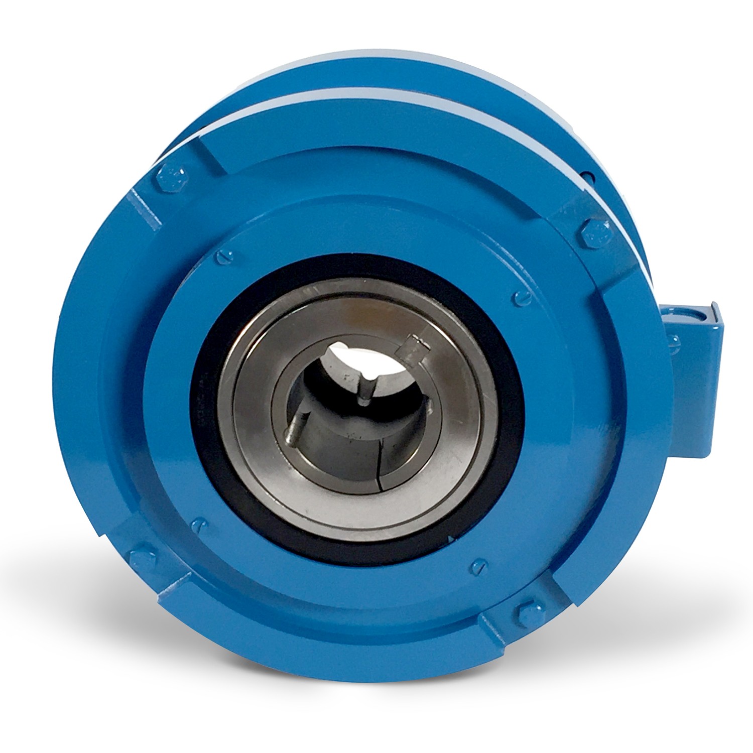
3D MODEL AVAILABLE UPON REQUEST
Available Cooling Types.
- Model 75MB90S convection cooled.
- Model 75MBA90S forced air cooled.
- Standard 90VDC coil. Available in other voltages to order.
Superior Torque.
- Extra stopping capacity including emergency stops.
Extra Power Handling Capacity.
- More slipp watts for tension control.
- Faster cycling rates.
- Softer braking.
- Controls higher speeds.
Best Configuration.
- Taperlock bushings accommodate .5 - 1.625 in. shaft diameters.
- Simple shaft mounting for convenient installation.
- Stock torque arms.
- Compact, space-saving.
Model 75MB90S / 75MBA90S
Data sheet
- Model
- 75MB90S / 75MBA90S
- Rated Torque (lb.-ft.)
- 75
- Mounting
- Shaft
- Type Of Cooling
- Convection
- Heat Dissipation at 1800 RPM (Watts) (5)
- 600 (CA) / 1100 (FA)
- Max Oper. Speed (RPM) (6)
- 2600
- Non-Excited Drag Torque (lb.-ft.)
- 2.0
- Inertia (WK (2)) Rotating Member (lb.-ft. (2)) x 10(-2) - OUTER
- -
- Inertia (WK (2)) Rotating Member (lb.-ft. (2)) x 10(-2) - INNER
- 65.0
- Wgt. Approx (lbs.)
- 60 (CV) / 70 (FA)
- Coil Data (Input 90VDC) - CURRENT AMPERES (4)
- 0.99
- Coil Data (Input 90VDC) - RESISTANCE OHMS @ 20 C
- 70
- Note (2)
- Coils for other voltage wound to order
- Note (3)
- Data given represents the average, continuous dissipation capacity of units operating under slip conditions
- Note (4)
- Applications requiring operation below 30 RPM should be referred to factory for evaluation
Download
5MB**S / 25MB**S / 50MB**S / 75MB**S Installation & Maintenance Manual
Download (207.8k)
5MB**S / 25MB**S / 50MB**S / 75MB**S Service Parts Information Manual
Download (1.91M)


