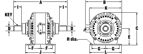
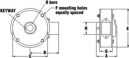
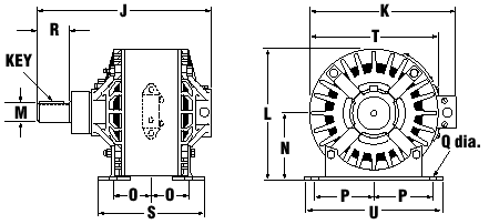
See Below for Magneclutch® and Magnebrake® Dimensional Drawings
Magneclutch® Dimensional Drawing - Base Mount

| Model | A | B | C | D | E | F | G | H | I | J | K | L | Key |
|---|---|---|---|---|---|---|---|---|---|---|---|---|---|
| 1MC90B | 7.22 | - | 4.56 | 0.380 | 2.62 | 0.62 | 1.25 | 0.28 | 1.19 | 1.98 | 3.11 | 3.50 | - |
| 5MC90B | 9.50 | - | 5.44 | 0.625 | 2.81 | 0.94 | 2.25 | 0.31 | 1.44 | 2.94 | 5.25 | 5.25 | 3/16SQ x 1.12L |
| 10MC90B-20 | 11.44 | 7.39 | 6.23 | 0.750 | 3.22 | 2.09 | 2.38 | 0.41 | 1.84 | 5.08 | 6.03 | 5.81 | 3/16SQ x 1.38L |
| 50MC90B-20 | 15.25 | 9.84 | 8.75 | 1.250 | 4.50 | 2.75 | 4.00 | 0.41 | 2.22 | 7.75 | 8.50 | 9.38 | 1/4SQ x 1.75L |
| 100MC90B-20 | 17.50 | 11.84 | 10.75 | 1.625 | 5.50 | 3.75 | 4.50 | 0.56 | 2.59 | 9.81 | 10.50 | 10.50 | 3/8SQ x 2.0L |
| 200MC90B | 20.62 | 14.69 | 13.25 | 1.875 | 7.00 | 5.25 | 6.25 | 0.69 | 3.00 | 12.00 | 12.50 | 14.00 | 1/2SQ x 2.25L |
Notes:
1. Physical appearance may vary between models.
2. Consult factory for dimensions of flange mounted, NEMA C-Face mounted, forced air cooled and water cooled units.
3. Recommended maximum shaft deviation from horizontal is 30 degrees. Above 30 degrees consult factory.
4. Shaft keys supplied with all units.
5. All dimensions in inches.
Magnebrake® Dimensional Drawing - Shaft Mount

| Model | A | B | C | D | E | F | G | H | Keyway | ||
|---|---|---|---|---|---|---|---|---|---|---|---|
| Holes | Studs | THD | |||||||||
| 5MB90S | 3.44 | 3.44 | 3.62 | .625 | 4.25 | 3 | - | #10-24 x 3/8DP | 2.84 | .88 | 3/16W x 3/32DP |
| 25MB90S | 3.69 | 4.57 | 5.88 | 1.125 | 6.25 | - | 3 | #10-32 | 2.63 | 2.88 | 1/4W x 1/8DP |
| 50MB90S | 4.66 | 6.62 | 8.41 | 1.750 | 9.03 | - | 4 | 1/4-20 | 3.16 | 2.63 | 3/8W x 3/16DP |
| 75MB90S | 5.91 | 6.62 | 9.34 | (8) | 10.01 | - | 4 | 1/4-20 | 5.13 | 6.88 | Taper Lock(8) |
Notes:
1. Consult factory for dimensions of forced air cooled units.
2. Recommended maximum shaft deviation from horizontal is 30 degrees. Above 30 degrees consult factory.
3. Bore adapters available for 25, 50 and 75 series brakes, consult factory.
4. Suitable torque arm required to prevent rotation. Mounting should be "floating".
5. Physical appearance may vary between models.
6. Shaft key supplied with all units.
7. All dimentions in inches.
8. Unit supplied with 1615B adapter - customer to furnish taper lock bushings.
Magnebrake® Dimensional Drawing - Base Mount

| Model | J | K | L | M | N | O | P | Q | R | S | T | U | Key |
|---|---|---|---|---|---|---|---|---|---|---|---|---|---|
| 10MB90B-20 | 9.60 | 7.39 | 6.23 | 0.750 | 3.22 | 2.09 | 2.38 | 0.41 | 1.84 | 5.08 | 6.03 | 5.81 | 3/16SQ x 1.38L |
| 50MB90B-20 | 11.75 | 9.84 | 8.75 | 1.250 | 4.50 | 2.75 | 4.00 | 0.41 | 2.22 | 7.75 | 8.50 | 9.38 | .25SQ x 1.75L |
| 100MB90B-20 | 13.50 | 11.84 | 10.75 | 1.625 | 5.50 | 3.75 | 4.50 | 0.56 | 2.59 | 9.81 | 10.50 | 10.50 | .38SQ x 2.0L |
Notes:
1. Consult factory for dimentions of forced air cooled units.
2. Recommended maximum shaft deviation from horizontal is 30 degrees. Above 30 degrees consult factory.
3. Shaft key supplied with all units.


